Time for another post in the series on Roland A-80 MIDI Keyboard Controller servicing. Previously:
- The Roland A-80 arrives
- Changing R43 to make the aftertouch more responsive
- Replacing the key bed “upper” felt
- Replacing the D4 key’s rubber dome switch
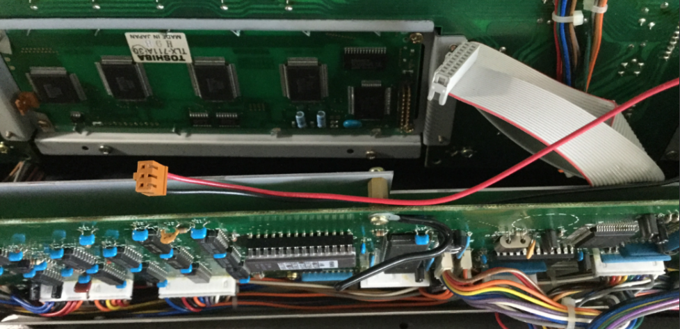
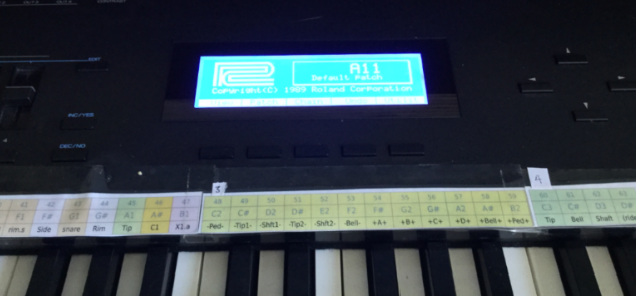
- Replacing the LCD display
The short:
- Use Velostat to replace the pressure-sensitive cells under each key.
- Change R43 to a variable resistor of about 27k and set it mid-way
- Enjoy.
The longer, illustrated version
Despite the R43 fix, the touch response has never really been usable. The mechanism Roland used clearly didn’t remain viable over time. The risk of screwing up the key bed completely has always deterred me from experimenting in this area.
And then, there was this thread on Computer Music Guide forum, “Roland A-80 (Aftertouch Repair)”. Back in 2014, noisevoid had the great idea to experiment with alternative pressure-sensitive rubber to see if they could restore touch-sensitivity to the notoriously unresponsive A-80 key bed. Their research identified a product from Zoflex as a possible solution…. and then they were never heard from again on that thread.
But the idea intrigued me, and after Syntaur alerted me that the “upper” key felt strip was back in stock, I decided it was time to go deeper. I placed an order for a sheet of the Zoflex product… and also did more research on pressure-sensitive materials.
One finding in particular looked very interesting: In 2016 Liam Lacey had implemented a “toy keyboard synthesizer” with pressure sensitivity using a product called “Velostat”. Intrigued, I ordered a sheet as an alternative.
Eventually the samples showed up. The Zoflex rubber sheet was about 1mm thick and quite “spongy” and quite expensive for a 10cm square sample, in beige. The Velostat sheet was larger, more like an A4 sheet of paper, and much thinner. And cheaper.
Here’s the plan:
- Replace R43 with a variable resistor to allow for sensitivity adjustment
- Remove the keys and the upper felt strips
- Lift the plastic pressure strips enough to insert samples of alternate product
- re-assemble loosely to test response
Replace R43 with a 100k variable PCB mount resistor
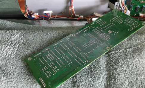
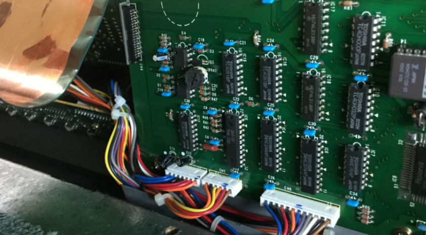
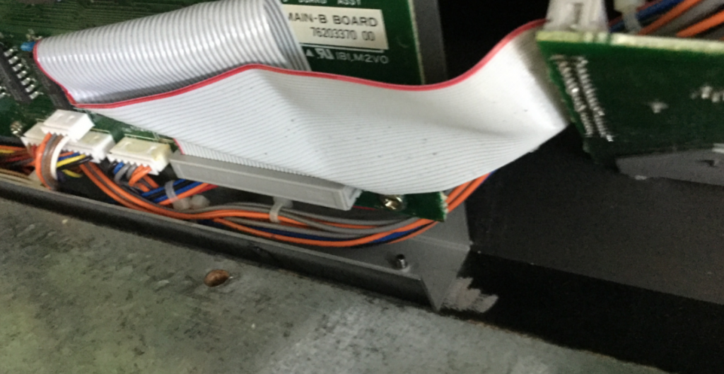
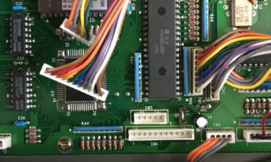
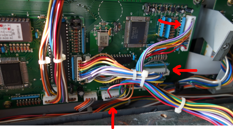
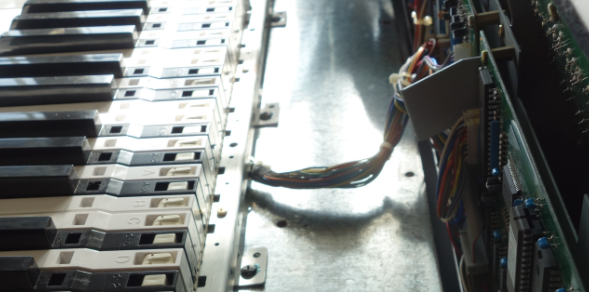
There’s no getting around it. Main Board A has to come out for desoldering. I’ve covered this process before. Six screws and several connectors need to be removed.
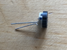
The odds of an alternative variable-resistance pressure membrane “just working” with the current 56k value seems unlikely. I obtained a small PCB-mount 100k resister and snipped off one of the outer legs. This gives us a replacement for R43 that will let us alter the resistance. I wasn’t sure this step was necessary but it seems prudent.
With that done, I re-assembled Main Board A back into position.
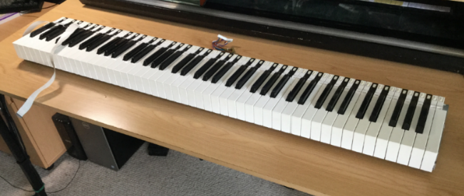
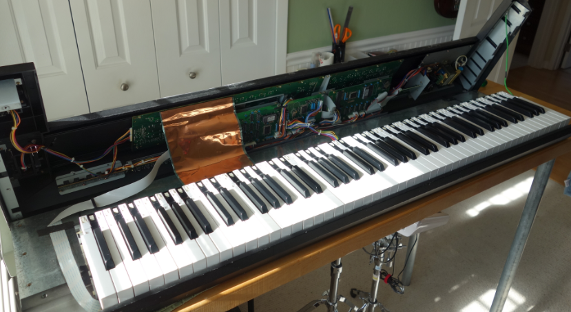
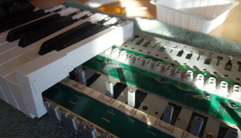
Remove the keybed assembly
Probably best to review my previous post on the subject.
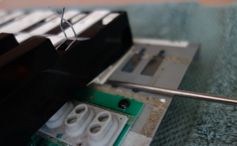
Digression: The Key Press Action
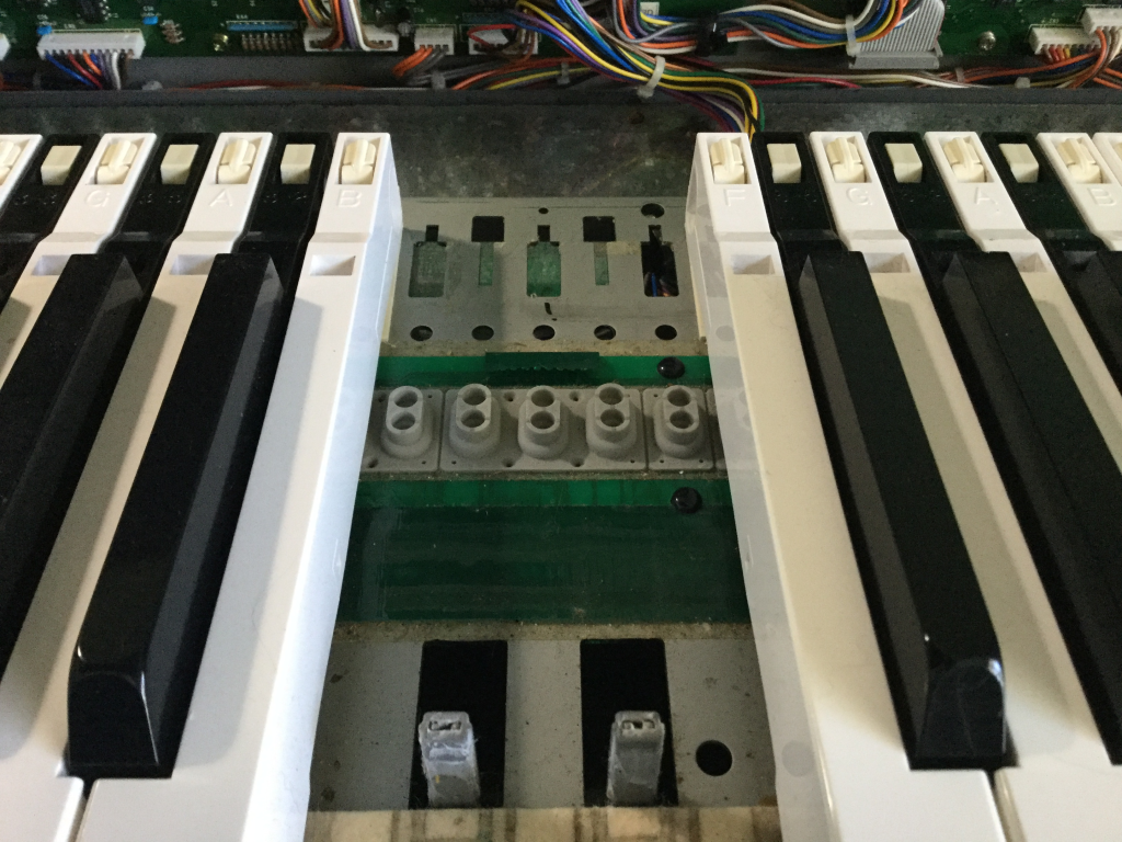
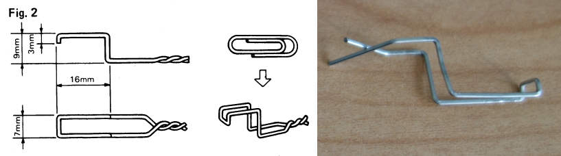
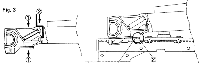
I created this animated GIF showing the mechanical action of a key press:
As you depress a key, the first thing that happens is that the grey rubber dome switch is activated. (You can see it on the right.) It has two contacts in it that closes two circuits in quick succession, indicating Note Velocity.
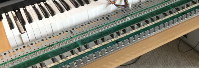
On the left you can see two felt strips that run under the keys. The black keys rest on the right-hand strip. The white keys rest on both strips. Under the felt strips are circuit contacts for each key press (white on the left, black on the right). Each contact is covered by a small rectangle of material that changes resistance with pressure. So, as you push down on the key, the resistance change is detected and translated to note pressure or “aftertouch”.
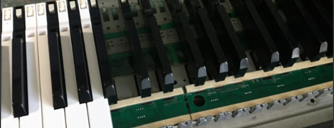
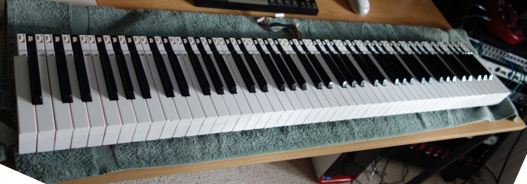
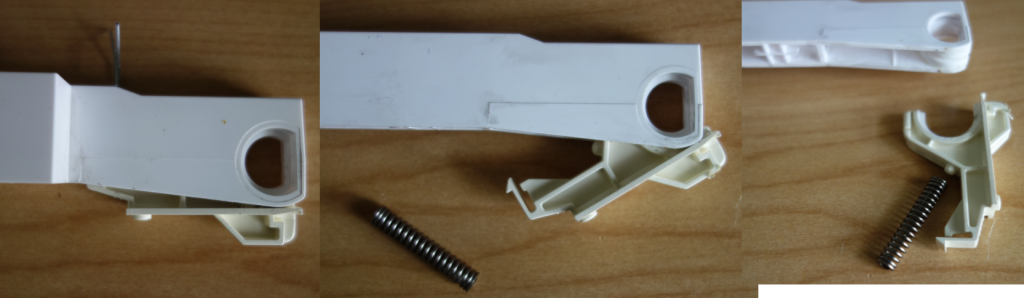
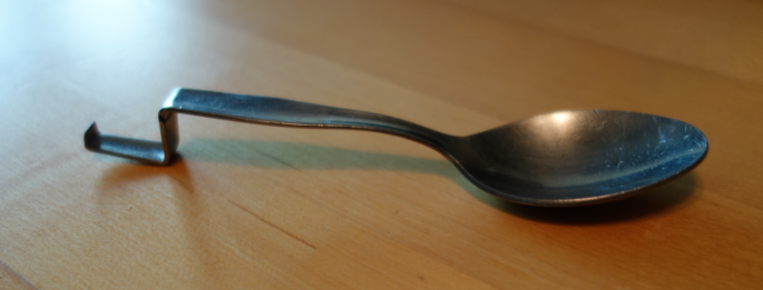
Remove the keys
This is where a key removal tool becomes very handy. I’ve actually made a short YouTube vid of the process:
With the keys removed, we can start finding out what is under those felt strips.
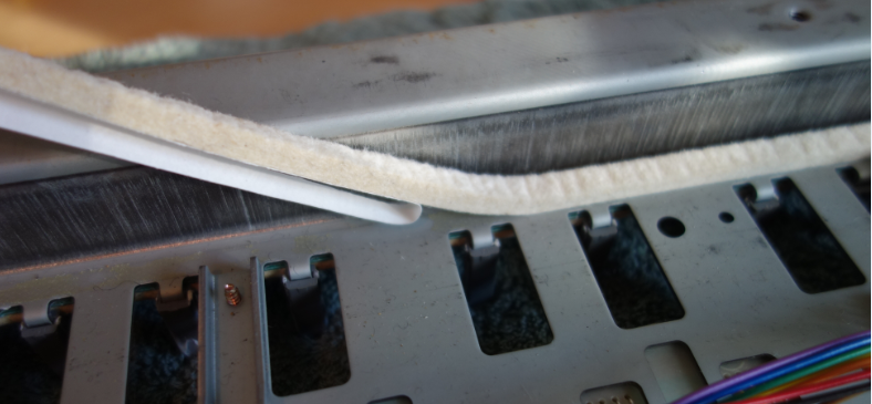
Remove the felt
At this point, my recommended procedure diverges from what I actually did. I was cautious and also not sure of what my next step would be. I wanted to remove the felt strip but leave the pressure strip in place. Also, I wasn’t planning on re-using the original felt strip, at least, not all of it. I figured I had a replacement strip that could be used for either the white keys or the black keys. I thought I only needed to keep 50% of the existing felt strips in re-usable condition.
The adhesive between the felt strip and the underlying plastic strip is quite strong and it was an awkward process to remove the felt intact while not also pulling the plastic strip away from the PCB. I really wanted to leave as much undisturbed and original as possible.
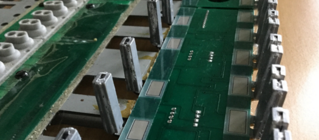
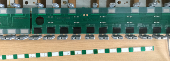
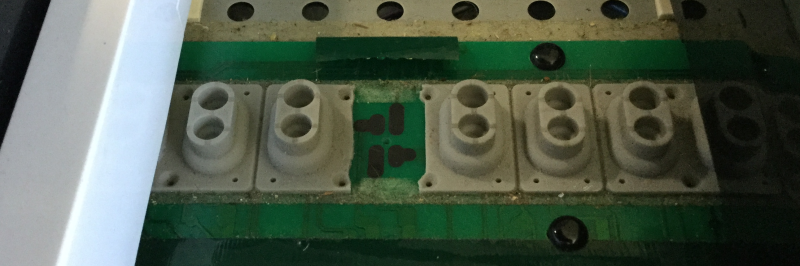
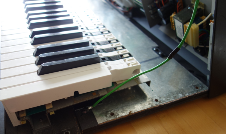
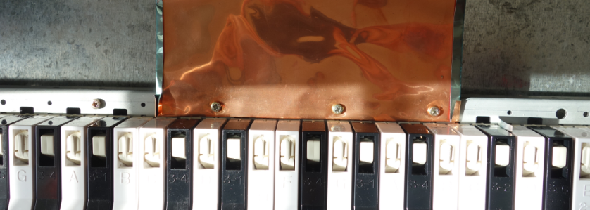
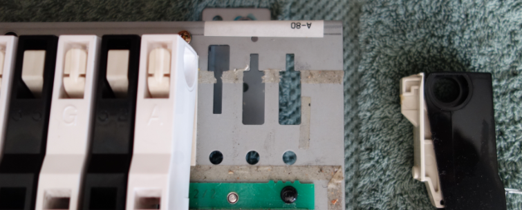
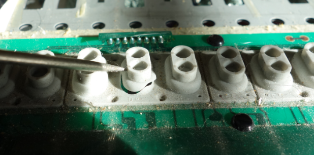
With the felt removed, we can see the plastic strips under which the pressure-sensitive resistive pads are mounted:
In hindsight, knowing that I was going to remove the plastic pressure strip eventually anyway, I should have removed the felt+plastic strip as a whole, and then carefully separated the felt from the plastic on a flat surface with more room to move.
Testing Substitute materials
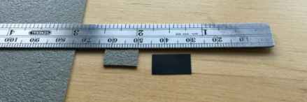
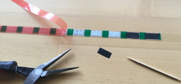
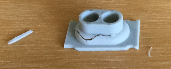
I carefully cut out little rectangles of the Zoflex and Velostat material:
I then pried up the end of one of the plastic pressure strip and inserted the sample rectangles under it so that they covered the two carbon contacts beneath. Keys B7 and C8 were to be the test cases. I’m sorry, I don’t have a picture of this configuration, you’ll have to imagine it.
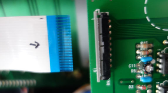
I then tacked the felt strip back in place temporarily and re-installed the two keys; lifted the key bed chassis back into place and re-connected it (remembering the aftertouch subsystem ribbon cable; easy to forget that one).
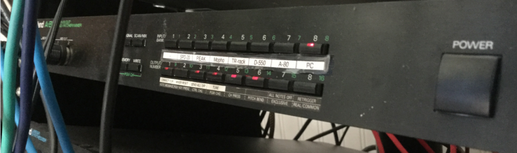
As a test patch, I initialized a program on the Novation PEAK and set the mod matrix so that aftertouch controlled the pitch of Osc1, bending it down a full octave at “maximum pressure”.
Results:
- The Zoflex key was unresponsive.
- The Velostat key was EXTREMELY sensitive to pressure.
Conclusion:
- Discard the Zoflex and experiment more with the Velostat.
WARNING: Turn off power to the A-80 before attempting to change the resistance of R43. Trust me. The A-80 will go berserk if you don’t.
By testing the change in touch response after each adjustment the value of R43, I could tell that reducing the resistance produced a corresponding decrease in sensitivity (a good thing!) A value of ~10k for R43 appeared to be optimal. Of course this will be subjective, your mileage may vary… I would think a varistor of 27k would probably give finer control.
What you shouldn’t do, and don’t need to know (Fast Forward)
- I used a crude method of tacking the Velostat rectangles in place
- I replaced the plastic pressure strips over the top and tacked them in place
- I used the 50% best original felt strips for the Black keys, flipping them over and using Kaisiking “red backed” double sided tape as adhesive.
- I used the brand new replacement felt strip for the White keys
- I assembled all of the key bed, and installed in the chassis
- I tested the unit.
- The Black keys worked great
- The White keys would not trigger reliably – the new felt + velostat was too thick, preventing the rubber domes from actuating.
- Also the difference in feel between white and black keys was disturbing.
- Removed key bed from chassis, removed all white keys
- Removed felt strip, which took the plastic strip with it because of the super-tacky double-sided tape I used
- Decided to use the remaining original felt strip for the white keys, and re-do the pressure strip “properly” while I was at it.
Converting the pressure strips
You should apply this process to both black and white keys.
Having peeled back and removed the plastic pressure strips, I carefully cleaned the carbon pads with 91% isopropyl alcohol.
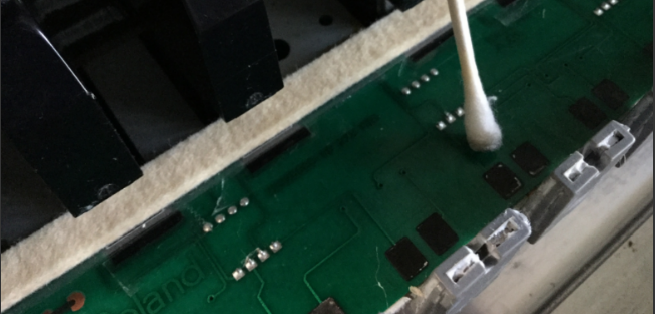
In the most-used keys (the central area), the original pressure pads had left white residue on the carbon pads. Use a light pressure and don’t go overboard, because you can remove carbon from the PCB and you don’t want to do that. Just clean them as much as you can, to encourage uniformity in touch response.
I then cleaned both sides of the plastic pressure strip with the isoprop, to remove as much of the residual sticky as possible.
The next step was to apply the double-sided tape to the resistive side – the side that will be laid over the carbon contacts on the PCB.
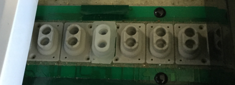
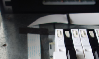
Using tools to keep use of greasy fingers to a minimum, I peeled the backing from the tape and placed the rectangles of Velostat over the pressure pads:
Next steps:
- Carefully place the pressure strip back on to the PCB, locating it very carefully so that the pressure pads are over the carbon contacts for each key.
- Firmly burnish the strip in place to encourage the adhesive.
- Place a second layer of tape over the top surface of the plastic pressure strip (in hindsight, I could have done this before placing the Velostat rectangles.)
- Peel the backing, and place the original felt strip over the pressure strip.
- Re-install the white keys
And that’s it. Wonderfully responsive, polyphonic aftertouch.

Recent Comments